|
|
|
PDF SRF08 Data sheet ( Hoja de datos )
| Número de pieza | SRF08 | |
| Descripción | UltraSonic Ranger | |
| Fabricantes | ETC | |
| Logotipo | ||
Hay una vista previa y un enlace de descarga de SRF08 (archivo pdf) en la parte inferior de esta página. Total 16 Páginas | ||
|
No Preview Available !
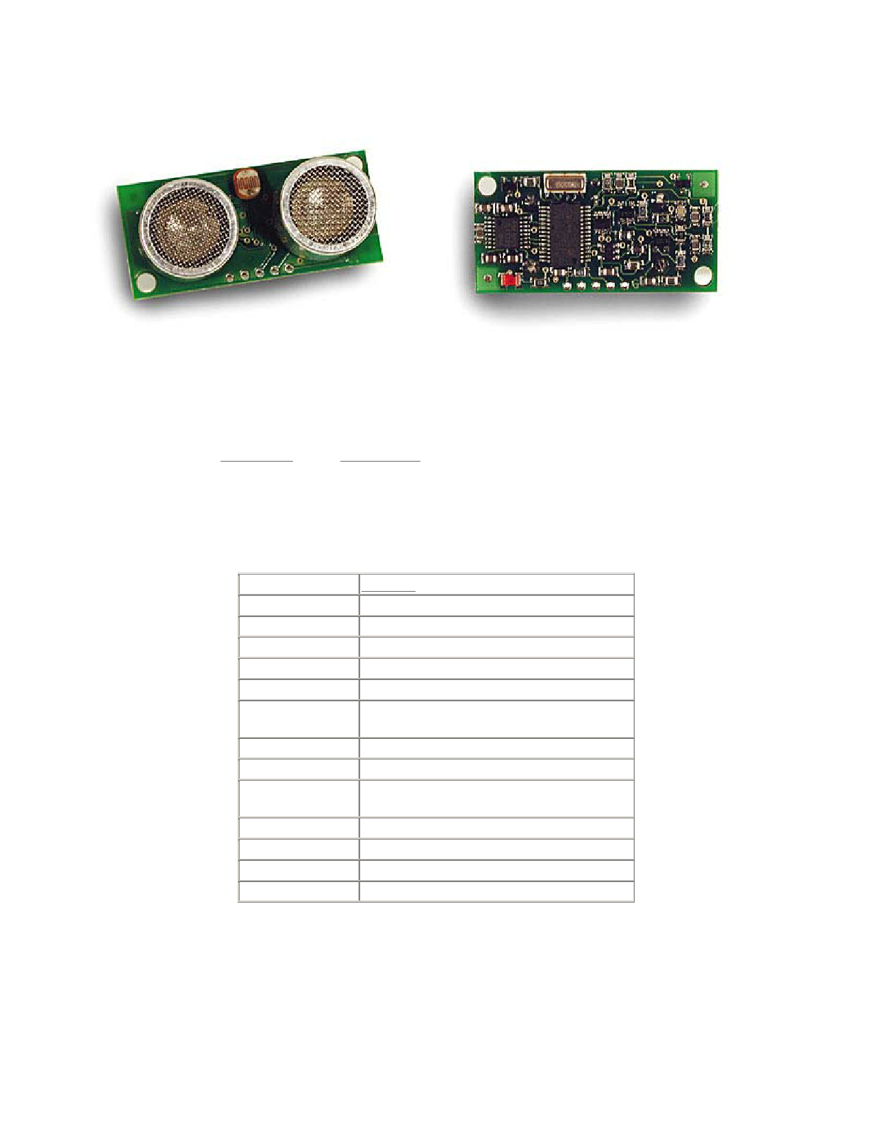
Devantech SRF08 UltraSonic Ranger
This Devantech high performance ultrasonic range finder is compact and measures an amazingly wide
range from 3cm to 6m. The SRF08 interfaces to your microcontroller via the industry standard IIC
bus. This ranger is perfect for your robot, or any other projects requiring accurate ranging information.
There is even a built-in light sensor on the front of the module. You can also get a nifty Lynxmotion
SRF08 Housing for one ranger or for two rangers.
Specifications
Beam Pattern
Voltage
Current
Frequency
Maximum Range
Minimum Range
Max Analogue
Gain
Connection
Light Sensor
Timing
Echo
Units
Weight
Size
see graph
5v
15mA Typ. 3mA Standby
40KHz
6m
3 cm
Variable to 1025 in 32 steps
Standard IIC Bus
Front facing light sensor
Fully timed echo, freeing host computer of
task
Multiple echo - keeps looking after first echo
Range reported n uS, mm or inches
0.4 oz.
43mm w x 20mm d x 17mm h
Specifications subject to change without notice
Mechatronic Systems
MechBot Sensor Overview, Page 1 of 16
1 page 
160 0xA0 1st in sequence to change I2C address
165 0xA5 3rd in sequence to change I2C address
170 0xAA 2nd in sequence to change I2C address
Ranging Mode
To initiate a ranging, write one of the above commands to the command register and wait the required
amount of time for completion and read as many results as you wish. The echo buffer is cleared at the
start of each ranging. The first echo range is placed in locations 2,3. the second in 4,5, etc. If a location
(high and low bytes) is 0, then there will be no further reading in the rest of the registers. The default
and recommended time for completion of ranging is 65mS, however you can shorten this by writing to
the range register before issuing a ranging command. Light sensor data at location 1 will also have
been updated after a ranging command.
ANN Mode
ANN mode (Artificial Neural Network) is designed to provide the multi echo data in a way that is
easier to input to a neural network, at least I hope it is - I've not actually done it yet. ANN mode
provides a 32 byte buffer (locations 4 to 35 inclusive) where each byte represents the 65536uS
maximum flight time divided into 32 chunks of 2048uS each - equivalent to about 352mm of range. If
an echo is received within a bytes time slot then it will be set to no-zero, otherwise it will be zero. So if
an echo is received from within the first 352mm, location 4 will be non-zero. If an object is detected
3m away the location 12 will be non-zero (3000/352 = 8) (8+4=12). Arranging the data like this should
be better for a neural net than the other formats. The input to your network should be 0 if the byte is
zero and 1 if its non-zero. I have a SOFM (Self Organizing Feature Map) in mind for the neural net,
but will hopefully be useful for any type.
Location 4
0 - 352mm
Location 5
Location 6
Location 7 Locations 8 - 35
353 - 705mm 706 - 1057mm 1058 - 1410mm and so on
Locations 2,3 contain the range of the nearest object converted to inches, cm or uS and is the same as
for Ranging Mode.
Checking for Completion of Ranging
You do not have to use a timer on your own controller to wait for ranging to finish. You can take
advantage of the fact that the SRF08 will not respond to any I2C activity whilst ranging. Therefore, if
you try to read from the SRF08 (we use the software revision number a location 0) then you will get
255 (0xFF) whilst ranging. This is because the I2C data line (SDA) is pulled high if nothing is driving
it. As soon as the ranging is complete the SRF08 will again respond to the I2C bus, so just keep
reading the register until its not 255 (0xFF) anymore. You can then read the sonar data. Your
controller can take advantage of this to perform other tasks while the SRF08 is ranging.
Changing the Range
The maximum range of the SRF08 is set by an internal timer. By default, this is 65mS or the
equivalent of 11 metres of range. This is much further than the 6 metres the SRF08 is actually capable
of. It is possible to reduce the time the SRF08 listens for an echo, and hence the range, by writing to
the range register at location 2. The range can be set in steps of about 43mm (0.043m or 1.68 inches)
up to 11 metres.
The range is ((Range Register x 43mm) + 43mm) so setting the Range Register to 0 (0x00) gives a
maximum range of 43mm. Setting the Range Register to 1 (0x01) gives a maximum range of 86mm.
More usefully, 24 (0x18) gives a range of 1 metre and 140 (0x8C) is 6 metres. Setting 255 (0xFF)
gives the original 11 metres (255 x 43 + 43 is 11008mm). There are two reasons you may wish to
reduce the range.
Mechatronic Systems
MechBot Sensor Overview, Page 5 of 17
5 Page 
Call PutPin(SDA, bxOutputHigh)
Call Delay(1.0)
' Delay just to be sure SRF08 is out of reset
Call I2cByteWrite(GB, CmdReg, &Ha0)
' 1st command in address change sequence
Call I2cByteWrite(GB, CmdReg, &Haa)
' 2nd command in address change sequence
Call I2cByteWrite(GB, CmdReg, &Ha5)
' 3rd command in address change sequence
Call I2cByteWrite(GB, CmdReg, SRF08_NEW_ADDRESS) ' The new I2C address
' That's the address changed, now perform SRF08 Ranging in an endless loop at the new address
Do
Call I2cByteWrite(SRF08_NEW_ADDRESS, CmdReg, RangeCmd) ' Start Ranging in Cm
Call Delay(0.07)
' 70mS wait for ranging to complete
Ldr = I2cByteRead(SRF08_NEW_ADDRESS, LdrReg)
' Read light sensor
Range = I2cWordRead(SRF08_NEW_ADDRESS, RangeReg) ' Read Range Register
debug.Print "LDR = "; CStr(Ldr); ", Range = "; CStr(Range)
Loop
End Sub
'--------------------------------------------------------------------------------------------
' I2C subroutines follow
'--------------------------------------------------------------------------------------------
' writes I2cData to I2cReg at I2cAddr
Sub I2cByteWrite(ByVal I2cAddr As Byte, ByVal I2cReg As Byte, ByVal I2cData As Byte)
Call I2cStart()
Call I2cOutByte(I2cAddr)
' send device address
Call I2cOutByte(I2cReg)
' send register address
Call I2cOutByte(I2cData)
' send the data
Call I2cStop()
End Sub
Function I2CByteRead(ByVal I2cAddr As Byte, ByVal I2cReg As Byte) As Byte
Call I2cStart()
Call I2cOutByte(I2cAddr)
' send device address
Call I2cOutByte(I2cReg)
' send register address
Call I2cStart()
' repeated start
I2cAddr = I2cAddr+1
Call I2cOutByte(I2cAddr)
' send device address with read set
I2cAck = False
' setup to send Nak
I2cByteRead = I2cInByte()
' get data byte with Nak
Call I2cStop()
End Function
Function I2CWordRead(ByVal I2cAddr As Byte, ByVal I2cReg As Byte) As UnsignedInteger
Set I2CWordRead = New UnsignedInteger
Call I2cStart()
Call I2cOutByte(I2cAddr)
' send device address
Call I2cOutByte(I2cReg)
' send register address
Call I2cStart()
' repeated start
Mechatronic Systems
MechBot Sensor Overview, Page 11 of 16
11 Page | ||
| Páginas | Total 16 Páginas | |
| PDF Descargar | [ Datasheet SRF08.PDF ] | |
Hoja de datos destacado
| Número de pieza | Descripción | Fabricantes |
| SRF01 | Ultrasonic range finder | ETC |
| SRF02 | Ultrasonic Range Finder | ETC |
| SRF02 | Ultrasonic Range Finder Tech | ETC |
| SRF04 | Ultrasonic Rangefinger Schematic | ETC |
| Número de pieza | Descripción | Fabricantes |
| SLA6805M | High Voltage 3 phase Motor Driver IC. |
Sanken |
| SDC1742 | 12- and 14-Bit Hybrid Synchro / Resolver-to-Digital Converters. |
Analog Devices |
|
DataSheet.es es una pagina web que funciona como un repositorio de manuales o hoja de datos de muchos de los productos más populares, |
| DataSheet.es | 2020 | Privacy Policy | Contacto | Buscar |