|
|
|
PDF KP1510 Data sheet ( Hoja de datos )
| Número de pieza | KP1510 | |
| Descripción | 8PIN IGBT GATE DRIVE PHOTOCOUPLER | |
| Fabricantes | Cosmo | |
| Logotipo | ||
Hay una vista previa y un enlace de descarga de KP1510 (archivo pdf) en la parte inferior de esta página. Total 14 Páginas | ||
|
No Preview Available !
cosmo
KP1510 Series
8PIN IGBT GATE DRIVE
PHOTOCOUPLER
Description
The KP1510 series consists of GaAlAs Light
emitter diode and an integrated. This unit is 8-lead
DIP package. KP1510 series is suitable for gate
driving circuit of IGBT or power MOSFET.
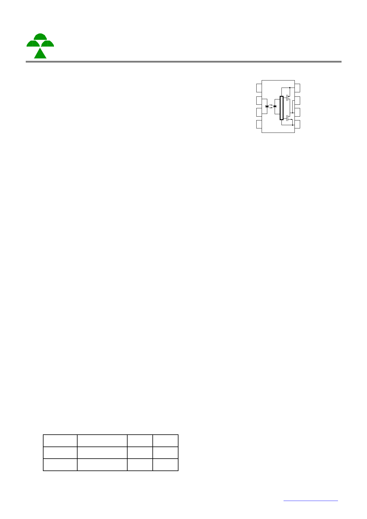
Schematic
1
2
3
4
8
7
6
5
Features
1. High noise immunity characterized by 25kV/μs
minimum common mode rejection(CMR)at VCM=1500V
2. 2.5A maximum peak output current
3. ICC = 5mA maximum supply current
4. Wide supply voltage range from 15V to 30V
5. Fast power switching application
– 500ns max. propagation delay
– 100ns min. PWD protection scheme
6. Under Voltage Lock-Out (UVLO) with hysteresis
7. Industrial temperate range: -30°C to 115°C
8. MSL class 1
9. Agency Approvals:
• UL Approved (No. E169586): UL1577
• c-UL Approved (No. E169586)
• VDE Approved (No. 40020973): DIN EN60747-5-5
Applications
• Industrial inverters
• Switch mode power supply
• AC/Brushless DC motor drives
• IGBT/Power MOSFET gate drive
Truth Table
1. N.C.
2. Anode
3. Cathode
4. N.C.
5. GND
6. Vo (Voltage Output)
7. Vo (Voltage Output)
8. Vcc
LED
OUTPUT
Q1 Q2
ON HIGH LEVEL ON OFF
OFF
LOW LEVEL OFF ON
*The use of a 0.1μF bypass capacitor must be
connected between pins 8 and 5 is recommended.
Cosmo Electronics Corp.
Document No. 69P51006.2
-1-
http://www.cosmo-ic.com
1 page 
cosmo
KP1510 Series
8PIN IGBT GATE DRIVE
PHOTOCOUPLER
Switching Characteristics
Parameter
Symbol
Test Condition
Propagation delay “L→H”
time “H→L”
Pulse width distortion
tPhl- tpLH
Propagation delay difference
Between AnyTwo Parts or
Channels (tPhl- tPlh) (7)
tpLH
tpHL
PWD
PDD
(Skew)
IF=7mA to 16mA
Rg=10Ω,Cg=10nF
F=10KHz,Duty Cycle=50%
Output rise time (10%-90%)
Output fall time
UVLO turn-on delay
tr
tf
TUVLO ON IF =10mA, VO>5V
UVLO turn-off delay
TUVLO OFF IF =10mA, VO<5V
Min.
0.1
0.1
—
Typ.
0.3
0.3
(Ta = 25℃)
Max. Unit
0.5 us
0.5 us
— 0.3
us
-0.35 — 0.35
— 0.1 —
— 0.1 —
— 0.8 —
— 0.6 —
us
us
us
us
us
Common mode transient
immunity at high level output
Common mode transient
immunity at low level output
∣CMH∣
TA=25℃,VCC=30V,
IF=10mA to 16mA VCM=1500V(8)
∣CML∣
TA=25℃,VCC=30V,
VF=0V VCM=1500V(9)
25
25
35 — KV / μs
35 — KV / μs
Notes:
1. Maximum pulse width = 10μs, maximum duty cycle = 1.1%
2. Derate linearly above 87°C, free air temperature at a rate of 0.77mW/°C
3. No derating required across temperature range.
4. Functional operation under these conditions is not implied. Permanent damage may occur if the device is
subjected to conditions outside these ratings.
5. Device is considered a two terminal device: Pins 2 and 3 are shorted together and Pins 5, 6, 7 and 8 are shorted
together.
6. 5,000 VRMS for 1 minute duration is equivalent to 6,000 VACRMS for 1 second duration.
7. The difference between tPHL and tPLH between any two KP1510 parts under same test conditions.
8. Common mode transient immunity at output high is the maximum tolerable negative dVcm/dt on the trailing edge
of the common mode impulse signal, Vcm, to assure that the output will remain high (i.e. VO > 15.0V).
9. Common mode transient immunity at output low is the maximum tolerable positive dVcm/dt on the leading edge of
the common pulse signal, Vcm, to assure that the output will remain low (i.e. VO < 1.0V).
10. Pulse Width, PW 1μs, 300pps
11. Exponential Waveform, IO(PEAK) ≦2.5A (≦0.3μs)
Cosmo Electronics Corp.
Document No. 69P51006.2
-5-
http://www.cosmo-ic.com
5 Page 
cosmo
Numbering System
KP1510 X (Y)
KP1510 Series
8PIN IGBT GATE DRIVE
PHOTOCOUPLER
Notes:
KP1510 = Part No.
X = Lead form option (blank、S、H、L )
Y = Tape and reel option (TL、TR、TLD、TRU)
Option
Description
S (TL) surface mount type package + TL tape & reel option
Packing quantity
1000 units per reel
S (TR) surface mount type package + TR tape & reel option
L (TLD)
L (TRU)
long creepage distance for surface mount type package +
TLD tape & reel option
long creepage distance for surface mount type package +
TRU tape & reel option
1000 units per reel
800 units per reel
800 units per reel
Recommended Pad Layout for Surface Mount Lead Form
1.Surface mount type
8-pin SMD
2.Long creepage distance
for surface mount type
8-pin L
1.9 1.9
8.3
Cosmo Electronics Corp.
Document No. 69P51006.2
- 11 -
10.7
Unit :mm
http://www.cosmo-ic.com
11 Page | ||
| Páginas | Total 14 Páginas | |
| PDF Descargar | [ Datasheet KP1510.PDF ] | |
Hoja de datos destacado
| Número de pieza | Descripción | Fabricantes |
| KP1510 | 8PIN IGBT GATE DRIVE PHOTOCOUPLER | Cosmo |
| KP1510H | 8PIN IGBT GATE DRIVE PHOTOCOUPLER | Cosmo |
| KP1510L | 8PIN IGBT GATE DRIVE PHOTOCOUPLER | Cosmo |
| KP1510S | 8PIN IGBT GATE DRIVE PHOTOCOUPLER | Cosmo |
| Número de pieza | Descripción | Fabricantes |
| SLA6805M | High Voltage 3 phase Motor Driver IC. |
Sanken |
| SDC1742 | 12- and 14-Bit Hybrid Synchro / Resolver-to-Digital Converters. |
Analog Devices |
|
DataSheet.es es una pagina web que funciona como un repositorio de manuales o hoja de datos de muchos de los productos más populares, |
| DataSheet.es | 2020 | Privacy Policy | Contacto | Buscar |